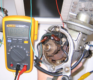
Test pickup coil for serviceability
G Pickup coil is used to measure speed and postion of the camshaft
<G Pickup coil, Blue wire>
NE Pickup coil is used to measure the speed and position of crankshaft.
<NE Pickup coil, Red wire>
Specifications Toyota | Actual Ω | Serviceable? | ||
G Pickup Coil | Cold | 185-275 | 238.4 Ω | O.K |
NE Pickup Coil | Cold | 370-550 | 469.2 Ω | O.K |
Specifications Toyota | Actual | Serviceable? | |
G Pickup Coil | Air Gap: 0.2-0.4 mm | 0.254mm | O.K |
NE Pickup Coil | Air Gap: 0.2-0.4 mm | 0.254mm | O.K |
Capture the signal waveform on a digital oscilloscope
As the reluctor approches to the stator and there is a smalles gap between them, the waveform reaches to a peak voltage. Then as soon the reluctor moves away from the pickup coil, the voltage decreased to opposite direction.(magnitec flux collapsed)
As the reluctor turns rapidly, it produces more voltage at a high frequency.
A-A': peak to peak voltages
B: wave time
A pulse generator consists of a stator and a rotor unit. The stator unit consists of a permanent magnet and a pickup coil. The pickup coil is connected to the ignition control or igniter by two wires. The rotor(reluctor) is made of soft iron and has a number of teeth.(e.g 4 teeth - 4 cylinder of the engine) As each tooth of the reluctor rotates past the pickup coil, a very small AC voltage is induced into the pickup coil. This small electircal pulse is used by the igniter and is sent to ECU to trigger the spark.
Pickup coils send an electrical signal to the ignition module to trigger spark and fuel injectors.
Hall-Effect Sensors
First experiment(As shown below, the signal pattern is not good)
Degrees turned | Voltage |
0° | 0.1V |
45° | 0.2V |
90° | 0.1V |
135° | 0.2V |
180° | 0.1V |
225° | 0.2V |
270° | 0.1V |
Hall-effect generator produces a digital pulse. This distributor uses tabs and windows to provide a swiching arrangement. When each of the tabs passes the hall-effect device by rotating the distributor shaft, a digital squre wave pulse is produced.(When a tab is passing through the air gap, it shunts the field and the device is switched on. When a window is in the air gap between the magnetic pole and the sensor, only a weak magnetic field reaches the sensor. So there is no signal)
Second Experiment to check for good signal pattern
Optical Distributor
Position | Voltage |
0° | 0V |
60° | 0.027V |
120° | 0.012V |
180° | 0.027V |
Optical distributor uses light as an electronic trigger. There is a light emitting diode on top of the protractor disc and there is a photodiode beneath. An interrupter disc between the LED and the phototransistor has slits that allow the light from the LED to trigger the phototransistor on the other side of the disc. When aligned with a slot, the light from the LED is allowed to shine through the slots in the chopper plate to the photodiode.(switch on) But as rotation occurs, the beam is cut until the next slot lines up between the two.(switch off)


No comments:
Post a Comment