98' Falcon headlamp wiring diagram
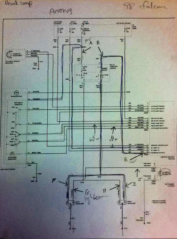
Reading circuit diagram-
1. Break into pieces
2. Trace current flow
What is a voltage divider?
In many circuits, it is necessary to obtain a voltage not available from the main power source. Rather than have multiple power sources for all needed voltages, we can derive other voltages from the main power source. In most cases, the needed voltage is less than the voltage from the main source, so we can use resistors in an appropriate configuration to reduce the voltage from the power source, for use in a small circuit.
Calculcate Vout, Vout1, Vout2 below circuits.

RT=20K
Vout=14 x 5/20=3.5V
Right side pic: R1=970R, R2=4K7, R3=100R
RT=5.77K
Vout1=12 x 4800/5770=9.983V
Vout2=12 x 100/5770=207.97mV
Practical
Fuel injector circuit

Component lists
Name | Qty | Unit price | Details |
| Resistor R14,R15 | 2 | $0.55 | 560R, 1/4W, 5% tolerance |
| Resistor R13,R16 | 2 | $0.55 | 2K2, 1/4W, 5% tolerance |
| LED | 1 | $0.30 | 5mm Red,VF=2.0V,IF=20mA |
| LED | 1 | $0.30 | 5mm Yellow,VF=2.0V,IF=20mA |
| Transistor | 2 | $0.31 | BC547 NPN, TO-92 |
| Conectoros | 1 | $1.50 | 4pin |
Calculations
To calculate the resistance of R14 and R15, we assume Vs = 12V, ID=20mA and VLED=1.8V.
(Refer to LED datasheet)
By ohm's law, R = V / I
R = (12-1.8) / 20mA = 510Ω (closest value: 560Ω)
To calculate the resistance of R15 and R16, refer to BC547 datasheet.
According to the datasheet, collector-emitter saturation voltage test condition IC=10mA, IB=0.5mA
In our circuit, the current of collector is 20mA. Therefore we multiply test condition by two.
Ic=20mA, IB=1mA
For the safety reason, we double the base current which is 2mA.
R = (5-0.7)/2mA = 2.15kΩ (closest value: 2.2kΩ)
By the way, my first calculation was based on gain from the datasheet.
β = IC / IB
IB = IC / β
IB = 20mA/110
= 181.82uA
R = (5-0.7) / 181.82uA = 23.65kΩ (closest value: 27kΩ)
Components layout on the board

<Drawn by using lochmaster>
.
How the circuit works
12 volts power is applied to No.1 connector. Then when 5 volts pulse signal is passed through No.3 connector, red LED lights on and off continuously. Because the base of the transistor is 0.7 volts more positive than the emitter of the transistor and 2mA base current flows, so collector current flows and LED lights on.(is said to be "the transistor is saturated")
When 5 volts pulse signal is passed through No.4 connector, yellow LED light on and off continuously.
The purpose of resistor R13 and R16 is limiting the base current of the transistor to prevent the transistor being damaged.
The purpose of resistor R14 and R15 is limiting the collector current to prevent LED being damaged.
Ref: http://www.youtube.com/watch?v=JTCgUY51g0s
http://www.youtube.com/watch?v=eVCYR4B7IZ8&feature=relmfu
Test Procedure


Problems
After soldering every components, I noticed that the resistors R13 and R16 were connected to the emitter of the transistors. Therefore, desoldered the joints and reconnected the resistors R13 and R16 to the base of transistors. Except the above problem, everthing was fine.
Reflection
If I had an opportunity to do the circuit again, I would check the size of the board first, then would make the layout of the board by using lochmaster. Further more, I would solder the component as I think about easy testing.
No comments:
Post a Comment